

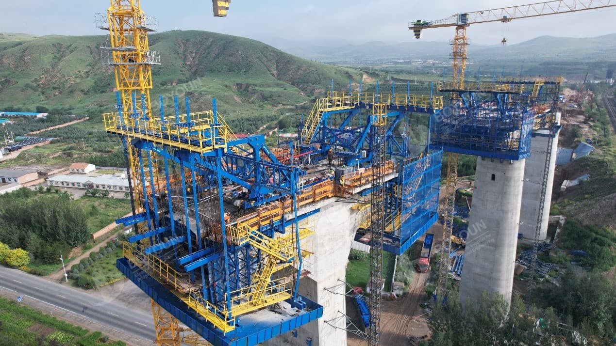
In Expressways construction, the key points of cantilever casting box girder construction with form traveler are crucial to ensuring structural safety, linear precision, and construction efficiency. Mastering these technical essentials directly impacts the durability and performance of the entire highway bridge. Below, we delve into eight core operational standards to guide practical engineering, offering professional insights for engineers and construction teams.
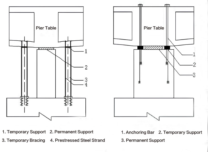
(1)For continuous beam construction, temporary supports must be installed on the pier top. Their function is to temporarily fix the pier and beam, resist unbalanced bending moments during cantilever casting with form travelers, bear the beam pressure when permanent supports are inactive, withstand tension and compression stresses caused by unbalanced loads during beam construction, and allow easy removal.
(2)The size and quantity of temporary supports must be determined through design stress calculations. Their anti-overturning stability coefficient must not be less than 1.5.
(3)Temporary supports are usually placed at the box girder webs on both sides of permanent supports. They can be made of reinforced concrete blocks or sulfur mortar blocks with a strength grade not less than C40. Steel bars or section steel are embedded in temporary supports to fix the beam and pier, or prestressed threaded bars are embedded in the pier body and anchored to the base plate of the pier table.
2. Permanent Supports
(1)Permanent supports shall be installed before laying the base form of the pier table. Before installation, check that the specification, type, model, and direction of the supports meet design requirements.
(2)Support pre-deviation: According to the closure sequence, the monitoring unit shall provide pre-deviation data in advance. During installation, pre-deviate the upper plate of the movable support. The pre-deviation value is calculated by the monitoring unit based on the expected closure time and temperature difference during support installation, and shall be set on-site as required.
(3)Installation of supports and grouting of anchor bolt holes: Supports anchor the upper plate to the main beam and the lower plate to the pier top bearing pad via anchor bolts. Before installation, measure the pier top bearing pad; clean debris and water in anchor bolt holes with an air hose.
(4)Mark the center lines of the bearing pad and the lower base plate of the support with red ink after centering. Adjust the support so that its center line aligns with that of the pad. Set steel wedges at the four corners of the support base plate to adjust the top elevation to meet installation requirements. Use gravity grouting (erect on-site brackets with small funnels on top, connect plastic hoses to anchor bolt holes, and use height difference to ensure dense grouting) to pour epoxy resin mortar into anchor bolt holes, tamping until the mortar exceeds the pad top by 3–4mm after compaction (Figure 1).

Figure 1: Schematic diagram of gravity grouting of support anchor bolts
(5)The anchor bolts of the support upper plate are directly cast into the main beam concrete. After installation, secure the bolts firmly to prevent falling during concrete pouring. If there is a conflict between the dense steel mesh at the upper plate and anchor bolt positions, prioritize the anchor bolts.
3. Construction of Box Girder Pier Table and block No.1
(1)The temporary consolidation design of the pier table shall withstand both tension and compression loads. If not specified in the design, easily detachable steel structures or high-strength concrete structures (for compression) combined with PT Bar (for tension) are recommended.
(2)The pier table is preferably cast in one pour. Before pouring, take measures to prevent upward floating of the inner form. If the beam section is too high to ensure quality in one pour, it can be cast in two layers along the height, with the interval between pours controlled within 7 days.
(3)If the partition wall thickness of the pier table is ≥1.5m, cooling water pipes should be installed to prevent excessive temperature differences between the interior and exterior due to hydration heat.
(4)The reserved offset for installing permanent supports at the bottom of the pier table shall be determined by calculation based on the difference between the scheduled closure temperature and the standard temperature specified in the design.
(5)Concrete shall be poured in layers symmetrically from the outside to the inside (from the block No.1 to the pier table). After pouring the base plate, pour the web and top plate in one go, with each layer thickness not exceeding 300mm.
(6)The setting time of concrete shall be determined based on the concrete volume and pouring rate of the pier table and block No.1.
(7)Supports for the pier table and block No.1 shall be preloaded as required.
4. Form Traveler Preloading
(1)For box girders constructed by cantilever casting, form traveler preloading tests shall be conducted, preferably in-situ.
(2)The test load shall be selected based on the most unfavorable working conditions for form traveler construction. Load levels include: initial state after form installation; loaded to completion of steel bar binding; loaded to completion of base plate concrete pouring; loaded to completion of web concrete pouring; loaded to completion of top plate concrete pouring; and overloaded by 20%. Records shall be kept for each stage.
(3)Static load tests preferably use the load pressurization method. Appropriate pressure testing methods can be selected based on the form traveler structure and on-site conditions.
(4)After the static load test, calculate the elastic and inelastic deformation at each point, compile a pressure test report, and the monitoring unit shall calculate the pre-lift value based on test data to determine the formwork elevation.
5. Construction of Cantilever Segments
(1)If the longitudinal slope is ≥2%, form travelers shall be equipped with limit devices to prevent longitudinal slippage.
(2)Strictly control the distance between the form traveler’s rear anchor point and the segment end face to reduce segment misalignment. The distance should be at least 200mm.
(3)Ensure the construction quality of anti-collapse steel bars and hook bars for prestressed tendons, and appropriately densify the positioning steel bars for corrugated pipes.
(4)Strengthen quality control over the installation of inner forms for beam segments (focusing on special-shaped forms for in-box prestressed tooth plates). Ensure accurate form positioning and tight joint assembly to prevent form expansion, grout leakage, excessive concrete volume in beam segments, and avoid significant deviations in line control elevation due to excessive volume.
(5)Pouring of cantilever segment concrete should be controlled using a directional three-way pump pipe. The maximum allowable unbalanced weight shall be based on data provided by the designer. If not specified, the concrete volume deviation should not exceed 1/4 of the segment weight or 20t.
(6)The cross-section of concrete box girder segments shall be chiseled, with a 10mm intact boundary retained outside the concrete cover during chiseling.
6. Construction of Side-Span Cast-in-Place Segments
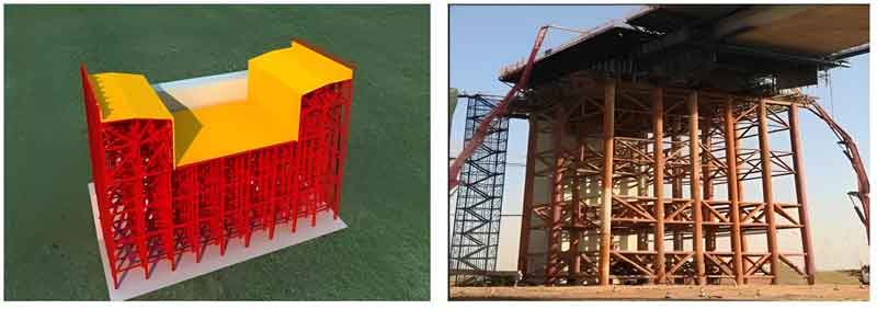
(1)Side-span cast-in-place segments can be constructed using steel pipe pile supports or full framing.
(2)If brackets are used for cast-in-place segments, their design must meet basic load-bearing and stability requirements, as well as the requirements for bearing eccentric loads of closure segments.
(3)Foundation treatment for supports must bear not only the load of cast-in-place segments but also the construction load of closure segments. The foundation on one side of the closure segment shall be appropriately reinforced to ensure sufficient bearing capacity.
(4)During construction of cast-in-place segments, pre-embedments and reserved holes related to closure segment construction shall be provided according to the closure segment plan.
(5)If the cast-in-place segment supports are entirely placed on the bearing platform, preloading is not required; otherwise, overloading preloading is necessary.
(6)Supports for cast-in-place segments shall be equipped with devices to ensure horizontal displacement under prestress application and temperature effects.
7. Construction of Closure Segments
(1)The closure sequence must comply with design requirements to ensure that the internal forces and alignment of the beam after closure meet design specifications.
(2)Closure segments can be constructed using form travelers, hanging frames, or supports:
l For form traveler construction: Pre-embed sling holes at the other cantilever end of the closure gap in advance, move the form traveler’s base form platform and outer form to the closure gap, hang them on the box girders of both cantilever segments, and remove the form traveler’s main truss. Since closure segments are shorter than ordinary segments, modify the form traveler’s formwork to adapt to the overlap requirements of cantilever ends on both sides and prevent misalignment.
l For hanging frame construction: The hanging frame structure must undergo design calculations. The specification, type, and mechanical properties of section steel must meet load-bearing requirements and allow easy installation and removal. Hanging points should be close to the box girder web and at least 50cm from the cantilever end. Hanging frames can only be removed after all prestressing of the closure segment is completed.
l For support construction: Supports must meet load-bearing requirements for strength, stiffness, and stability.
(3)When adjacent T-structures are 2–3 segments away from the closure gap, conduct through surveys to check the elevation and axis deviation of the two cantilever segments, which must be within allowable limits.
(4)Before constructing the closure segment, measure the center line and elevation of the cantilever segments. If the deviation of the center line or elevation exceeds 15mm, take corrective measures approved by the design unit, monitoring unit, and supervision unit. Corrective measures may include weighting, temporary prestressing, or jacking, which can only be removed after prestressing of the closure gap is completed.

Schematic diagram of closure block construction
(5)Before locking the closure gap of continuous (rigid frame) concrete box girders, determine whether cantilever end weighting is needed to adjust stress and alignment based on the monitoring unit’s calculations. If weighting is required, the weight shall be as specified by the monitoring unit.
(6)The closure gap shall be locked at the designed theoretical closure temperature. If the actual temperature does not meet the requirement, take measures such as continuous water spraying on the beam body, placing ice blocks inside the beam to cool it, or applying counterforces to the closure gap after calculation.
(7)Steel supports for temporary locking can be external or internal. For internal supports, consider the impact of concrete placement and vibration, and open grouting and vibration holes on them. For external supports, install them at the web chamfers. Steel supports for closure gap locking must undergo design calculations. The temporary locking force must ensure that the closure gap concrete bears no tensile or compressive forces from the start of pouring to longitudinal prestressing, preventing cracking.
(8)Steel supports for the closure segment exert significant constraints after locking. Therefore, fix one end of the steel bars before locking the supports, and weld or bind the other end immediately after locking.
(9)Closure segment concrete shall be poured under the temperature conditions specified in the design drawings. If not specified, choose days with small temperature changes and pour during the low-temperature period of the day, completing the process quickly. After pouring, promptly cure the concrete with moisture.
(10)Shrinkage-compensating concrete is recommended for closure segments to enhance crack resistance.
(11)After the closure segment concrete reaches the design strength, conduct prestressing as early as possible. Develop a special prestressing procedure to ensure uniform force application, preventing local damage to beams or plates due to excessive stress. After prestressing, complete the system conversion of the continuous beam as required.
(12)During prestressing, check for cracks at the rear end of the closure segment’s tension tooth plate.
(13)The removal of temporary pier-beam anchors shall be done symmetrically and evenly to ensure gradual and uniform release. Measure the elevation of each beam segment before removal, monitor elevation changes during the process, and stop work immediately if abnormalities occur to identify the cause.
8. System Conversion
(1)After completing the closure segment, remove the temporary pier-beam consolidation supports in the design sequence to complete system conversion.
(2)Adopt different removal methods based on the type of temporary supports:
l For sulfur mortar supports: Heat the resistance wires embedded in sulfur mortar to soften it, then chisel it away.
l For high-grade mortar supports: Drill a row of holes around the supports with a small geological drill, then use a pneumatic pick to remove the remaining parts, or directly chisel them with a pneumatic pick.
(3)After removing temporary supports, release the fixing bolts between the upper and lower plates of permanent supports to allow free sliding, completing the structural system conversion.
Every key point in continuous beam construction must be implemented rigorously, and high-quality formwork equipment is the foundation for ensuring the quality of each process. As a professional bridge formwork manufacturer with years of experience in the industry, we can customize suitable formwork solutions according to your project needs, providing full support from design to production, and helping solve problems related to precision and efficiency in construction. Contact us now to obtain exclusive technical consultation and quotations, and let professional formwork safeguard your bridge project!

We focus on turn-key solutions and types of formwork for Bridge and Viaduct Construction at home and abroad since 2006.


International Department: Room 2507-2508, Tower C of Wanda Plaza, Tongzhou District, Beijing 101118, China.
+86-13021287080
info@boyoun.cn

