

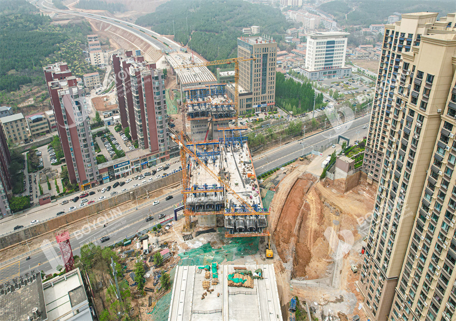
Balanced catilever construction with form travelers is widely applied in municipal road and bridge projects due to its features of simple operation and lightweight structure. However, the cantilever form traveler structure imposes high requirements on fabrication and installation, with its key technical points mainly reflected as follows:
(1) Technical key points of form traveler fabrication: Before designing the form traveler, the construction drawings must be carefully verified to avoid quality issues of the cantilever form traveler caused by drawing errors. Construction personnel should also conduct performance tests on the fabricated cantilever form traveler; only after all service performances of the form traveler meet the standards can it be allowed for use by municipal road and bridge construction personnel.
(2) Technical key points of form traveler installation: To ensure the safety of the balanced cantilever system, the installation work should be carried out only when all materials and processing equipment are available. The current mainstream installation process for cantilever form travelers is: main frame → anchoring system → suspension system → bottom formwork frame → side formwork → inner formwork (to be implemented after steel bar binding) → end formwork → tensioning platform.
(3) Safety protection for form traveler installation in municipal road and bridge projects:
First, the safety of the cantilever form traveler itself. During the installation process, the installation structure directly affects the safety of the form traveler. Therefore, after the completion of the basic structure construction, a thorough and detailed inspection must be conducted; only when it is confirmed that the structure meets the designed load-bearing capacity and has high reliability can the form traveler installation proceed.
Second, the safety risks of form traveler installation to the surrounding environment. During installation, the area around the construction site should be cleared to ensure that irrelevant personnel do not gather in the installation zone, preventing injuries caused by falling objects during the installation process.
2. Technical Key Points of Preloading Test
(1) Key points of preloading test preparation: Before conducting preloading on the form traveler, the rear anchoring system of the form traveler must be effectively fixed first. The main components to be fixed are the front crossbeam and the rear pressure system; anchoring is the commonly adopted fixing measure for these two systems. It is essential to ensure that the tie rods of the front crossbeam and the rear pressure system are under uniform stress. These two systems are critical devices for ensuring the safe operation of the balanced cantilever; uneven stress between them may cause serious safety issues such as instability and inclination of the form traveler during operation, which not only affects construction quality and efficiency but also endangers the safety of construction personnel.
(2) Technical key points of the preloading process: The preloading process of the cantilever form traveler is a key link to test its installation performance. The preloading process should be divided into multiple levels in detail. The levels are determined based on the actual load-bearing capacity of the cantilever form traveler and the time limit of the preloading activity. Usually, each level is 10 tons, and the higher the load-bearing capacity of the form traveler, the more levels are required. The preloading process must be carried out simultaneously on both form travelers of the balanced cantilever, with equal preloading weights applied to each side.
3. Technical Key Points of Concrete Pouring and Prestress Tensioning
(1) Key points of pouring technology: After the formwork is in place, the bottom formwork is first used to support the crossbeam and longitudinal beam at the bottom of the form traveler. Since the height of each beam segment needs continuous adjustment, it is unnecessary to form an integral structure between the inner formwork and the frame. Instead, the final pouring method should be determined according to the specific conditions of the box girder section. During the pouring process, a hole should be reserved in the middle of the top plate to ensure that concrete can enter the box girder and help the uniform distribution of the bottom formwork. When the box girder is relatively high, a deceleration hopper should be used for concrete transportation. Secondary pouring is generally carried out based on the actual completion status of the bottom formwork, side formwork, and steel bars.
(2) Prestress tensioning: When the strength of the concrete specimen reaches 80% (48MPa), the end formwork and outer formwork are removed to perform tensioning of the prestress system. The tensioning process adopts the double-control principle (controlling both stress and elongation) to ensure they meet the design requirements. After tensioning, the pipeline is cleaned before grouting; strict control is imposed on various technical indicators of the grout to ensure grouting pressure, which is maintained for 5 minutes. Both ends of the grouting holes are sealed with wooden plugs.
4. Technical Key Points of Form Traveler Walking
The main steps are as follows:
(1) Use a jack to loosen the cable-stayed belt, fix the front supporting beam and outer formwork on the poured beam body with a chain block, and then remove the cable-stayed belt.
(2) Dismantle the rear suspension rods of the inner and outer sliding beams, loosen other constraints on the main beam, and replace the compactor with a pressure wheel device.
(3) Use a chain block to slide the main beam system (together with the sliding beam) to the design position of the beam segment to be poured, anchor the main beam system to the poured beam body, and connect the inner and outer sliding beams to the rear crossbeam.
(4) Loosen the constraints of the bottom basket and side formwork on the beam body, lower the bottom basket and side formwork onto the outer sliding beam, then release their constraints, and pull them to the design position of the beam segment to be poured through the outer sliding beam using a chain block.
(5) Install the cable-stayed belt and lower rear anchor belt, adjust the formwork, perform limit anchoring, and bind the steel bars of the bottom and web plates.
5. Technical Key Points of Closure Construction
Closure construction is a crucial part of municipal road and bridge construction, and its quality will have a profound impact on the overall performance and future operation of the structure. Therefore, in municipal road and bridge closure construction, it is first necessary to thoroughly understand the construction environment, analyze factors such as materials and temperature that may affect the closure, select a reasonable closure method, and conduct corresponding mechanical calculations for the closure work. After the closure joint is locked, the specific closure work should be carried out promptly: first, firmly bolt or weld the rigid support section at the closure joint to the embedded parts at the beam end of the municipal road and bridge; then connect the other end of the outer rigid support to the beam; and immediately follow with the tensioning of temporary prestress tendons.
6. Conclusion
In summary, cantilever form traveler (balanced cantilever) construction is widely used in current municipal road and bridge projects, featuring simple operation and lightweight structure. However, since the form traveler is often located at high altitudes during construction and the cantilever structure itself is relatively complex, it is necessary to strengthen the analysis of its technical key points and quality control.

We focus on turn-key solutions and types of formwork for Bridge and Viaduct Construction at home and abroad since 2006.


International Department: Room 2507-2508, Tower C of Wanda Plaza, Tongzhou District, Beijing 101118, China.
+86-13021287080
info@boyoun.cn

