
 Russian
 French
 Spanish
 Arabic
 Thai
Thai Indonesian

Following the discussion of the four major design principles for formwork systems in the previous article, once the concepts of safety, adaptability, economic efficiency, and operability are established, the key to success becomes how to translate these principles into specific technical parameters and structural solutions. This article focuses on the design details of formwork systems for bridge pier and abutment construction, presenting actionable and implementable technical points, from material selection to structural connections, and then to the mechanical calculations of support systems.
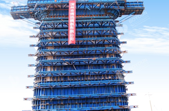
Steel formwork, using Q235 or Q355 steel as the base material with a panel thickness of 3-6mm, can withstand large loads and resist deformation. Back ribs use channel steel or square steel to enhance overall rigidity, making it suitable for long-span, high-load pier and abutment construction scenarios. Its high turnover rate offers significant long-term economic advantages. Wood formwork, mainly bamboo plywood or film-faced plywood with a panel thickness of 12-18mm, is lightweight and easy to process. Using wooden ribs as backing, it can flexibly adapt to special-shaped section piers and abutments or temporary construction needs. However, its service life is shorter, making it more suitable for short-term or small-scale projects. Aluminum alloy formwork, primarily using 6061-T6 profiles, weighs only one-third of steel formwork, reducing handling and installation difficulty. Its turnover rate can reach 300 times, and its high standardization makes it suitable for batch construction with tight schedules. Composite formwork, such as the steel-frame plywood system, provides stable rigidity support from the steel frame, while the plywood facing can be flexibly cut according to the pier and abutment shape. This balances rigidity and adaptability for special shapes, making it suitable for multi-span variable cross-section bridge piers and abutments, reducing the cost of remaking formwork for different sections.
The panel thickness is determined based on calculated concrete lateral pressure. Mechanical analysis ensures the panel deflection control value is not greater than 1.5mm, preventing excessive deformation during pouring that would affect the pier and abutment appearance dimensions. For back rib and support system design, optimize the spacing of back ribs and layout of tie rods. Use material mechanics formulas to back-calculate the component dimensions of back ribs and bolts, ensuring uniform load transfer and preventing structural damage due to local stress concentration. Joint treatment can use tongue-and-groove design to enhance sealing, or a combination of flat joint plus sealing strip. The compression rate of the sealing strip must meet usage requirements to block leakage channels for concrete slurry, while also preventing step offsets after pouring that would affect the pier and abutment surface flatness. In joint design, use curved transition structures at corners to disperse stress, preventing joint cracking under long-term stress. Special-shaped formwork is processed using CNC cutting technology to precisely control component dimensions, ensuring the formwork closely matches the designed shape of the pier and abutment.
For vertical and horizontal member design, calculate the axial force on vertical members, shear force on horizontal members, and the overall stability of the support system. Based on the calculation results, determine reasonable spacing and step distances for vertical and horizontal members, ensuring vertical members can bear vertical loads and horizontal members can effectively transfer lateral forces, avoiding the risk of instability and collapse of the support system. When setting diagonal braces and tie rods, control the angle between diagonal braces and the ground within the range of 45° to 60°. This angle range maximizes the lateral displacement resistance of the diagonal braces. The spacing of tie rods should be designed based on the material's tensile strength. Use double nuts and backing plates at both ends for fastening to enhance connection reliability, preventing tie rod loosening leading to support displacement. For foundation treatment, the formwork support area needs concrete hardening to ensure a foundation bearing capacity of no less than 150 kPa. At the same time, set up drainage ditches around the hardened ground surface to promptly drain rainwater or construction water, preventing the foundation from becoming waterlogged, which would reduce its bearing capacity and affect the stability of the support system.
The selection of materials, the design of connections, and the verification of support systems together form the core technical essence of formwork design. A well-designed formwork system is the prerequisite for efficient construction and intrinsic safety. However, a perfect design still needs strict construction management to be realized. In the next article, we will move from the design drawings to the construction site, focusing on "Safety Control Measures for Bridge Pier and Abutment Formwork Construction", covering the entire process control from pre-construction preparation to high-altitude work protection, providing you with practical safety guidelines.

We focus on turn-key solutions and types of formwork for Bridge and Viaduct Construction at home and abroad since 2006.


International Department: Room 2507-2508, Tower C of Wanda Plaza, Tongzhou District, Beijing 101118, China.
+86-13021287080
info@boyoun.cn

